Help

Blue Integrator Tutorial

Welcome to Blue Integrator!  This tutorial steps you though the creation of a simple project that involves the key elements of working with Blue Integrator:

  • Creating Schemas for incoming and outgoing Messages
  • Creating a Map between the two Message Schemas
  • Creating the Ports for incoming and outgoing Messages
  • Creating a Workflow to control the Message processing, and binding

We will assume you have installed and configured Blue Integrator to use a database and a server, the server is running, and Blue Integrator is ready for use.

The project we will create in this tutorial is relatively simple.  It receives a Message from an application that contains information about a customer’s order.  From that order, we want to extract information about what the customer ordered and send it to an inventory application that handles the shipping of the order.  To accomplish this relatively simple process, we need to inform Blue Integrator of the format of the incoming Message (presumably from a Website or order clerk), process the order Message according to some simple rules, and create an outgoing Message to the inventory application that contains specific information required for that purpose.  We could also create a Message to the billing department about the order, as well as sending a Message to a master database tracking all events, b
ut for the purposes of this tutorial we’ll restrict ourselves to handling the incoming and outgoing Messages.

Creating the schemas

The first step in this project is to create a Schema that defines the structure of the incoming Message containing the customer order information.  We then need to also create a Schema that defines the content of the outgoing Message to the inventory application.  We’ll define both of these Schemas as XML, though Blue Integrator also supports positional, delimited and binary files.

To create the incoming Message Schema, click the Schemas item in the Blue Integrator Explorer tree control, and then click the New button in the Schemas pane.  This will open the Schema Editor window.

The Schema Editor is laid out in three sections.  The left section shows a hierarchical tree view of the Schema as it is being created.  The middle section shows the (manually entered or system-generated) XSD. The right section is the Properties form for modifying the properties of an XML element selected in the tree-view 

You can work with the Schema Editor either in XSD or tree mode.  Tree mode is the easiest to work with, so we’ll use it here.

Start by clicking on the Schema title at the top of the left pane and select Create Child Element from the menu. A new element, indented from the Schema title, appears.  You can edit this element to rename it to something useful.  We’ll call it CustomerNumber (we’ll assume each customer has a unique number in a customer database that contains their personal information such as address and name). Since all departments in the company have access to the customer database, using the unique customer number on all messages works well.  Then, each application that needs to use the customer’s name and address can query the customer database using the CustomerNumber and obtain that information.  Keeping those details out of each Message cuts down on Message size and prevents corruption issues.


You can create another element by choosing Create Sibling Element from the popup menu from the CustomerNumberelement, and name that one CustomerItem (to keep things simple we’ll assume only one item is in each order; if multiple items are ordered, separate Messages are created for each).  As you work with the Schema, you’ll see the middle pane gets populated with the XSD representation of the tree view in the left pane:

We’ll create a new sibling element for ShipBy (indicating how the shipment is to be sent), as well as PayBy (a string value which indicates the customer’s method of payment; we do not need to worry about the details here). Finally, we’ll create an element called Dates. To illustrate how an element can have subelements, we’ll use the pop-up menu from the Dates element to create subelements by selecting Create Child Element and then have subelements for OrderDate (the date the order is places) and ShipDate (the date the customer would like to have the order shipped, in case there is a need for delay or just-in-time reception).

The Schema Editor looks like this now:

We need to set an attribute for the order number next. CustomerItem is, in this example, always going to be an integer number (reflecting a number in a catalog or Website, for example).  So, the data type associated with CustomerItem needs to be set to an integer.  To do this, highlight CustomerItem and, in the right pane, select the DataTypeproperty.  An arrow appears at the right edge of the field that opens to a drop-down menu.  Select xs:int as the data type. Do the same for the CustomerNumber, which will always be an integer too (for rapid lookup in the database). Finally, the ShipDate and OrderDate fields need to be set to use xs:date as the data types.  (Note that there is a data type called simply Dates but this actually relates to the Dates type we have defined, which is actually a pair of dates.  Select xs:date instead).

The XSD representation in the middle pane will update to reflect the data types you have chosen (notice how CustomerNumber has changed from type of xs:string to xs:int):

Save the schema by selecting File | Save from the Schema Editor menu.  Choose a descriptive name for this schema such as CustomerOrder. Close the Schema Editor.

The next schema we need to create is the outgoing Message’s schema.  This goes to the inventory processing application and needs to contain the CustomerNumber, CustomerItem, and ShipBy information. The inventory application doesn’t need to know about the PayBy method, or the dates.  We assume that, when an item is shipped from the inventory system, a separate message is sent to Blue Integrator providing this information.

To create the new schema, click on the New… button in the Schemas window, and create child elements for CustomerNumber, CustomerItem, and ShipBy.  We’ll also create a new sibling element called ProcDate (type xs:date) that contains the date the order was sent to the inventory application, allowing for an audit trail to be created. Finally, we’ll add a new element called OrderTrackingNumber (type xs:int) which contains a unique identification number for this transaction, again for auditing. Then save this new schema under the name InventoryRecord.

At this point, there’s no relationship between the CustomerNumber in the CustomerOrder schema and the CustomerNumber in the InventoryRecord schema. The names being identical has no effect on the relationship, and we could have called either element anything we wanted.  However, using the same name emphasizes the relationship between the two elements when we do create a relationship. That relationship gets defined in a Map, which we’ll look at next.

Defining a map between two schemas

A Map defines a transformation between two Message formats (typically from one Schema to another), in our case it describes the transformation applied to a Message between incoming (order) and outgoing (inventory) stages.  In this project, we’ll use a Map to transform the CustomerOrder schema into a message going to the inventory application using the InventoryRecord schema.  A Map simply defines the rules for populating the fields of the incoming message into those of an outgoing message, and can include steps for adding, changing, or removing content. Each Blue Integrator Map has one Schema applied to an incoming message and one Schema applied to the outgoing message, though these can be the same Schema, or can be the RAW (untyped) Schema.

To create a Map, click on the Maps item in the Blue Integrator Explorer tree window and then click New at the bottom of the right pane to open the Map Editor:

The Map Editor is laid out in four sections for (from left to right) the input schema document tree, the mapping detail pages (colored light blue), the output schema document tree, and the Functoid palette and Properties.

The first step is to set the source and destination Schemas.  This done by clicking the Select Source Schema… and Select Destination Schema… links in the headers of the Map editor’s first and third panes. For the input schema use CustomerOrder (it will appear on the drop-down list showing all defined Schemas). For the destination Schema select InventoryRecord.  The Map Editor now shows the schemas of the source and destination Schemas:

To indicate that the CustomerNumber in the source schema is to be passed to the destination schema without any changes, click on the black dot in the left side of the page pane and hold down the mouse button.  The cursor will change to crosshairs.  Now, holding down the mouse button, drag the crosshairs to the CustomerNumber dot on the destination schema and release the mouse button. A line will appear between the two, indicating that the source schema element is mapped directly to the destination Schema element:

The CustomerItem and ShipBy elements need to also be connected in the same way, so drag the elements together across the page detail pane.

If we needed to perform any manipulation on the elements, such as joining two strings together, performing mathematical changes to a value, or converting data types, just to name three simple examples, we could add a Functoid to do that task.  We will use a functoid for the outgoing Message, since we need to populate the ProcDate element (which shows the date the message was sent to the inventory application) with the current date.

To use a Functoid, you drag the functoid from the right pane onto the page pane. This will allow you to specify the parameters that the Functoid will use.  For ProcDate, in the right pane of the Map Editor, scroll through the list of Functoids until you come to the Date/Time Functoid section, then using the cursor, click on Now (Date)  and drag that functoid to the page pane. You can place the Functoid anywhere you like.  To customize the Functoid, you can double-click on it to display its properties, but this simple Functoid doesn’t need any changes to function.  Drag a line from right side of the Now (Date) Functoid item on the page pane to the InventoryRecord (destination schema) ProcDate black dot (the left side of any Functoid is the input, and the right side is output).  The map now looks like this:

Finally the OrderTrackingNumber needs to be assigned a unique ID number for auditing purposes.  In practice this could come from another database, and we could look this up using a combination of Functoids (including the Database Functoid, DataSet Table Selector Functoid and TableLookup Functoids) or some custom code (Code Functoid), but for this example we will just use the constant value 0 to indicate that the field hasn’t yet been populated.  To do this, drag a Constant Functoid onto the map page (from the Constant Functoids group), and double-click it.  Enter 0 as the value. Now drag from the right of this Functoid to the OrderTrackingNumber item in the InventoryRecord tree.

Finally, save the map under the name InventoryAppMessage and exit the Map Editor.  The next step after defining the Schemas and Map is to create the Receive and Send Ports by which data will enter and leave the system..

Creating the Ports

You will need both a Send and a Receive Port defined. The Receive Port will receive the CustomerOrder message and the Send Port will send the InventoryOrder Message.  In this case, we’ll assume that the Messages are actually going to arrive and be sent as separate files, one file per customer order or inventory request. To define these Ports, start with the Receive Ports option on the Blue Integrator Explorer, and then click New at the bottom of the right pane to display the Receive Port Configuration Form:

The Port Name can be anything descriptive, such as OrderPort.   Expand the Transport list by clicking on the arrow at the right side of the field and select the FileReceive option.  The dialog will immediately add a tab called FileReceive that lets you select the directory that the file will be placed into. Use the Browse button to locate or create the directory in which the incoming message files will be placed. Then, go back to the General tab. Next, click the Schema drop-down list arrow and choose Select from the options, then select CustomerOrder for the schema:

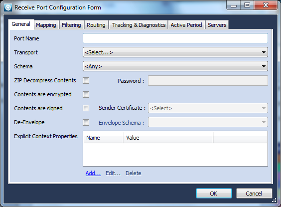
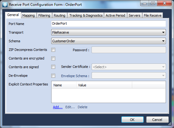
There are other options you can select that perform different actions or define the format of this incoming file Message, but we’ll assume a very simple file format for now.  The last step is to define the Server that is to be used for this message.  Click the Servers tab and select the proper server by placing a check in the box next to the Server’s name. If no Server is specified, the Port cannot run.  Finally, click the OK button to finish defining the incoming port.

The same process is used for the 
 Send Port.  Click on Send Ports in the Blue Integrator Explorer, click New, and the Send Port Configuration Form will appear.  Fill in the Send Port information, selecting a folder for the files to be sent to be placed in:

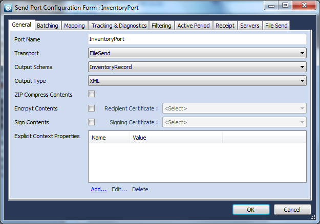
Again the last step is to define the Server that is to be used for this message.  Click the Servers tab and select the proper server by placing a check in the box next to the Server’s name. If no Server is specified, the Port cannot run.  Finally, click the OK button to finish defining the outgoing port.

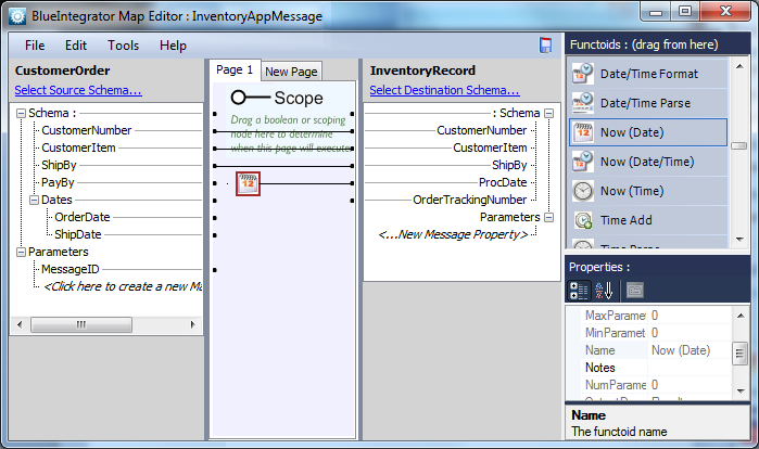
Now the Schemas, Maps and Ports are defined, we need to define a Workflow that actually takes care of processing the messages.

Defining Workflow

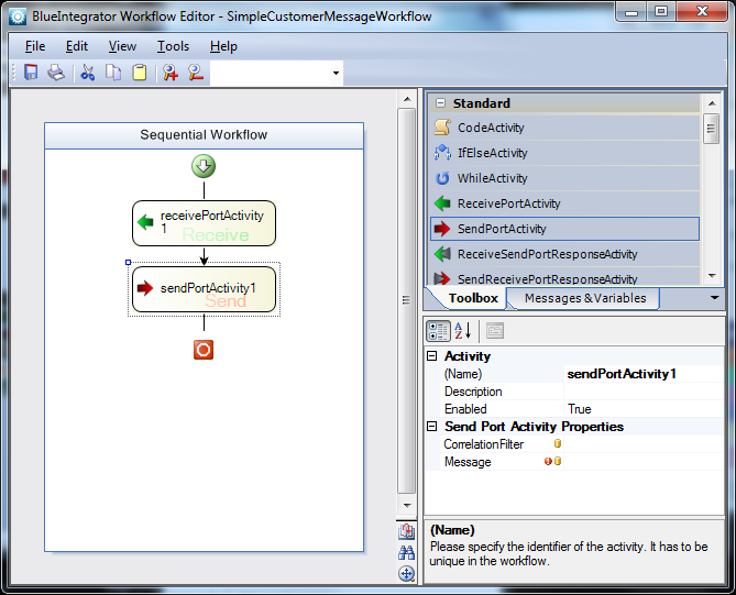
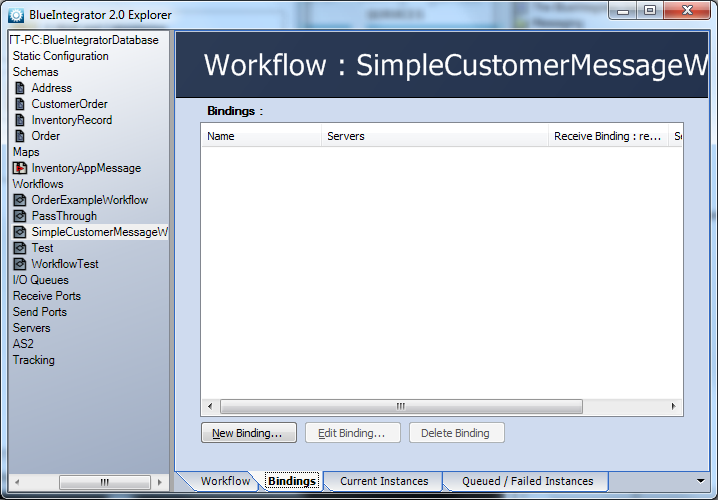
Workflows process Messages in specific ways, triggered by a number of different criteria.  In order to execute, a Workflow must be bound (meaning the Receive and Send Message Activities must be linked to physical Receive and Send Ports).  When a Message arrives at a Blue Integrator Receive Port bound to a Receive Port Message Activity, Blue Integrator checks whether an existing Workflow instance applies (based on Correlation filters).  If not, a new Workflow instance is created. So, every Workflow (except those designed to be invoked explicitly from other Workflows) must contain at least one Receive Port Message Activity.  Workflows are designed in the Workflow Editor.

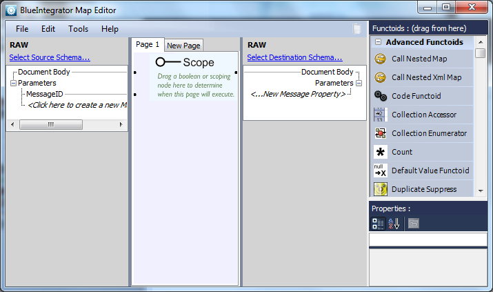
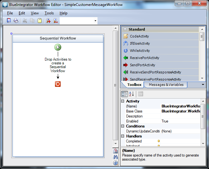
To define a Workflow for this project, click on the  
 Workflows item in the Blue Integrator Explorer tree, then click New at the bottom of the right pane and provide a name for the Workflow in the dialog that appears.  After entering a name, the Workflow Editor appears (this process may take a few seconds):

To create the Workflow, we need to tell Blue Integrator that a message will be coming in through a ReceivePortActivity, some processing is to occur, and then a message will be sent with a SendPortActivity. (The ReceivePortActivity is triggered when a message is received on the Receive Port, and the SendPortActivity triggers the sending of a message through the Send Port.)  So, we need to drag a ReceivePortActivity and a SendPortActivity from the right pane’s Toolbox onto the Sequential Workflow pane between the start and end icons so the Workflow looks like this:

We also need to drag a Map Activity inbetween the Receive and the Send Activities – this activity will transform the CustomerOrder Message into an InventoryRecord.

To hold the contents of the incoming message, we need to declare a variable.  To do so, click on the Messages & Variables tab next to Toolbox, then click on [Click to create a new Message…]. Replace the generic MessageName with a descriptive name such as CustomerMessage. A Select associated Message Schema dialog appears, and you can select the CustomerOrder schema from the drop down list:

To assign the CustomerMessage message to the ReceivePortActivity, click on the ReceivePortActivity box in the workflow pane, and in the Properties sheet in the lower right pane, select the Message property. This will display a drop-down list where you can select CustomerMessage. This associates the message with the ReceivePortActivity.

Now, a new message for the SendPortActivity can be created.  Create a message called InventoryMessage associated with the InventoryRecord schema, and then assign that message to the Message Property of the SendPortActivityWorkflow item.

Finally select the map InventoryAppMessage for the Map property of the MapActivity from the drop-down.  Select CustomerMessage and InventoryMessage respectively for the InboundMessage and OutboundMessage properties of this activity.  Here we are saying that we want to map from CustomerMessage to InventoryMessage using the map InventoryAppMessage we previously defined.

Now Save the Workflow.

Workflows can embed much more sophisticated logic, including conditional, looping and rule logic, and the execution of VSTA code. Custom Workflow activities can be created as well.  For this simple tutorial, we’ll leave the Workflow as it is.  Close the Workflow Editor.


Wrapping it up

At this point, you’ve defined the Schema for Messages that will arrive at the Receive Port, how those Messages will be processed according to the Map and Workflow, and the schema of Messages being sent through the Send Port whenever a Message is received in the Receive Port.  Of course, this is a simply example and you can create very complex logic flows and processing instructions for Messages, as well as perform many tasks on an incoming Message.  For more information, see the Blue Integrator Help file, and the Blue Integrator Web site for recent information.

The final stage is to create a binding between the Ports and the Workflow.  To do this, select the Workflow in the Blue Integrator Explorer tree, and select the Bindings tab.

Click the New Binding… button.  The Binding form appears.

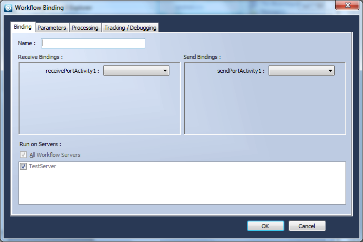
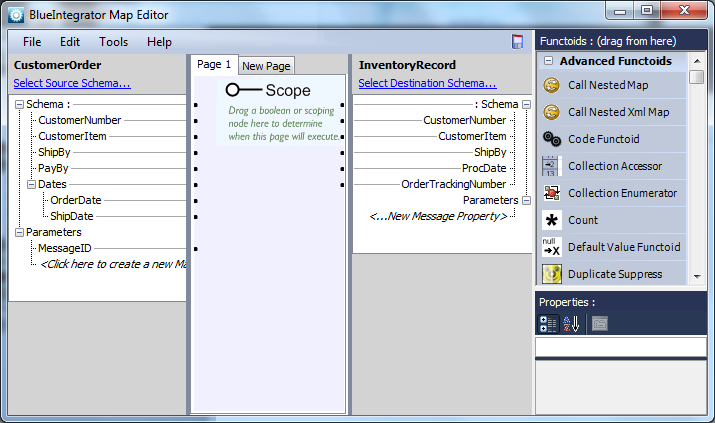
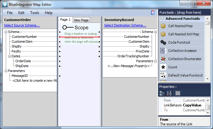
Give the Binding a name, and select the two ports previously created (OrderPort and InventoryPort) respectively as the binding for receivePortActivity1 and sendPortActivity1.  Click OK.

The final stage is to Enable each of the the two ports (by right clicking it in the Blue Integrator Explorer tree, or using the Enable link on the Port page in the Blue Integrator Explorer), and then copy a test order file into the folder location specified for port OrderPort.
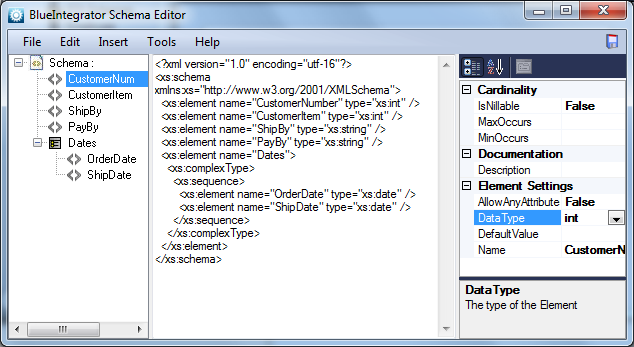
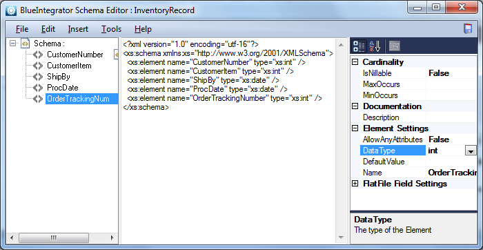
NOTE You can create a test file in the Schema editor using the Tools | Generate Sample XML Documentmenu item.

An associated inventory file should be generated in the folder location specified for port InventoryPort.  If the file doesn’t disappear from the input location, double check that the Receive Port is enabled and the Server is running. If it disappears but doesn’t reappear at the output location, double check that the Send Port is enabled and the Server is running, and also check the Tracking log for errors. You can access the Tracking log by selecting the Tracking node in the Blue Integrator Explorer tree.